Meeting the Demand for a New Generation of Flexible and Agile Manufacturing Facilities: An Engineering Challenge

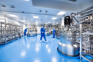
Flexible pilot facility with a 350L stainless steel bioreactor and a 1,000-L single-use bioreactor.
Classical stainless steel installations in purpose-built facilities dominate the global capacity for commercial biopharmaceutical manufacturing. Early facilities that were designed for single-product processes are now aging, putting them on the investment radar for upgrades to enable manufacturing diversity, and allow more efficient facility use. More than ever before, global engineering leaders are confronted with complex strategic and financial decisions when they seek to invest capital in new flexible pharmaceutical facilities or flex-grading aging facilities for supply of pipeline products. Manufacturing facilities today are in a more flexible continuum than were facilities 20 years ago.

Figure 1: Flexibility continuum
This flexibility continuum (Figure 1) can be broadly captured at four levels. Starting with process flexibility, that takes into account production mode, mix, scale, and volumes. Ultimately, process-level flexibility must translate into line definition and number of production trains. At suite-level flexibility, suite configuration encapsulates process flexibility such that future options can be exercised with minimum intervention to facility structure. If a company must integrate that into an existing site master plan and must reserve options for future expansion, then that can lead to an evaluation of construction methods. All of the above influence investment outlays, where management boards strive to balance capital spending with the degree of flexibility required.
From an engineering point of view, flexibility refers to flexible use of manufacturing suites by design to seamlessly and rapidly adapt to changes in a manufacturing process (e.g., multiple products) and the ability to handle varying volumes of production. Table 1 lists classical flexible manufacturing examples.
Well-targeted single-use technology (SUT) application introduces design flexibility through various options that can rapidly reconfigure a process sequence and scale after a project definition is established (something that is very challenging with stainless steel configurations). SUT brings operational flexibility by simply renewing the product-contact lining of manufacturing equipment.

Figure 2: A guided decision processes for single-use technology applications (1)
Renewal of equipment lining with single-use components is the game-changing advantage. SUT addresses good manufacturing practices (GMP) cleaning and carryover concerns and allows for agility with rapid start-up and changeovers for a given product portfolio. However, designing for process and suite-level flexibility also increases project complexity and escalates total project cost if stakeholders’ expectations are not well managed and aligned in the project definition (PD) phase. A guided decision process during PD phases helps manufacturers understand and communicate the risk-benefit of SUT applications (Figure 2).
The challenge faced by architectural, engineering, and consulting (AEC) companies in the PD phase is developing a common-denominator facility concept that can accommodate a broad scenario from a capacity model. Often, the flexibility appetites of operational heads are much higher than what are actually needed.
The aggregate flexibility wish list generated from working teams must be rationalized with iterations of project cost, with possible compromises and increased complexity. Consequent value engineering and optimization can lead to an overlap of different activity streams as well as shared facility features and resources. As a result, flexibility gets redefined under a set of constraints. Such constraints could compromise both capacity and compliance. For this reason, decision support for new manufacturing facilities is seen as part of an integrated planning process with key stakeholders.
Flexibility–Agility Dual Objective with Single-Use Technologies
The high (but less predictable) quantities of pipeline products and the increasing pressure to commercialize products faster call for a new generation of manufacturing facilities that focus on flexibility and agility. Smarter ways of planning and foreseeing future needs, structuring best practice approaches, and implementing visualization/simulation tools all support an engineering process. Such strategies enable development of effective solutions for maintaining flexibility. Methods that reduce complexity and risk of fast-track engineering projects are key competitive parameters for biopharmaceutical manufacturing facilities.

Figure 3: Flexibile facility concept
Flexible manufacturing with SUTs is a continuing trend. Some estimates report that two-thirds of new products being tested in early clinical trials are manufactured using single-use systems. Although investment in existing capacity and need for large-scale capacity might still favor manufacturing with traditional stainless steel installations, tactical use of single-use technologies in classical stainless steel facilities (e.g., in seed train stages) can offer flexibility levers (Figure 3).
The subsequent process baseline developed jointly by a manufacturer and AEC partner defines the manufacturing configuration in the new facility. Together with the capacity model, this exercise is the precursor to development of various flexibility options, such as designs for future flexibility but in discrete implementation phases (known as capital expediture or capex phasing).
On SUT projects, AEC companies must adopt a different design and execution approach because of reduced dependencies of single-use systems from stainless steel, hard-pipe distribution networks and building construction. Engineering work packages (e.g., bioreactors and ultrafiltration systems) become simplified and more “equipment centric” than stainless steel system equivalents, which tend to be more hard wired.
Although fewer system interfaces simplify engineering specifications, they may not necessarily simplify a project overall. Any SUT work package simplification advantage achieved by uncoupling equipment from hard-piped distribution networks conveys over to intensive SU process integration activities in the design and engineering phases. That is often overlooked and underestimated. Process integration involves specification of SU fluid transfer paths and aseptic connections for a complete process train. The scope and magnitude of activities associated with process integration could be bigger than the sum of all main SU unit operations. Just as with stainless steel networked facilities, specification of SU process transfer paths with SUT is an engineering activity until handover, after which it becomes part of operations. In addition, just as with stainless steel networked facilities, a fully specified SU flow path once validated is not amenable to uncontrolled changes. Thus, validated SUS production trains should be considered as “fixed” as stainless steel equivalents, and the impact of component changes needs to be performed according to established change control procedures.
On SU facility projects, AEC companies typically take a structured approach (1) to identify and rationalize SU connections, holds, transfers, and so on (Figure 2). That results in a bill of materials of components and assemblies. Well-designed SU assemblies are the building blocks of “process closure” and enhance the degree of flexibility of SUT equipment for multiproduct manufacturing. Working within given processes, single-use technologies are tuned to the extent feasible from both an implementation and financial perspective. For example, the footprint of a 2,000-L single-use bioreactor is not drastically larger than that of a 500-L single-use bioreactor. By reserving space for fitting a cell culture area with extra bioreactors, users can achieve a capacity expansion (e.g., from two times 500 L for early clinical material to six times 2,000 L for commercial production).
Flexibility is reflected in smart use of suite space for process operations, reserved workflow routes, and readiness for room classification changes. Such measures help manufacturers to install and switch process equipment as needed as well as work with different SUT suppliers.
Project Definition and Conceptual Development

Figure 4: Project definition sets the direction for AEC project phases
Management strategic plans typically extend to 10 years into the future. Strength of decision making is only as good as the accuracy of a forecast and capacity model. For biopharmaceutical products, the low predictability of pipeline candidates implies that many key decisions for capital allocation must be made under uncertainty. Some risks can be offset by designing manufacturing facilities with the required degree of flexibility. The most successful projects are those that have evolved during project-definition and conceptual-design stages to address market uncertainties and deliver to a company’s strategic objectives (Figure 4). Project definition encompasses all decision-support activities that enable management to decide on strategic, market, operational, facility, and capital aspects of a project.

Figure 5: Impact of decisions in conceptual design
AEC partners use a manufacturer’s project definition preamble to collaborate with stakeholders during the conceptual design (CD) phase. The rigor of that phase cannot underemphasized. Capital expended is relatively small during early stages, but the ability to affect a project’s alignment with strategic needs and financial maneuvers is significant. Typically, 70–80% of total investment cost (TIC) is committed by the end of conceptual development, with the expenditure of <1% of TIC (Figure 5). So a business plan must explore and analyze different process options to achieve strategic alignment. Once a flexibility consensus is reached during the CD phase, the design basis is established and triggers cross-disciplinary engineering activities.
Changing the project definition at later stages is a costly approach. Yet many companies hasten through the CD phase under the pressure of project timelines (without evaluating options) and then are stymied at the total investment cap that can bring a project to a halt.
Although project definition is often a manufacturer’s own internal exercise, conceptual development is a joint effort with user groups and AEC partners. To help start a project on the right track from the beginning, project team members must have the depth of experience to anticipate and deal with the breadth of changes and ambiguity inherent in complex projects. It is not uncommon to see manufacturers make their own operations people responsible for formulating the requirements for engineering design, even though they are not equipped with adequate project engineering controls.
The conceptual design phase can introduce a project risk-management strategy that highlights the most critical issues and the design choices to be made. Every business case is founded on a set of needs and opportunities that uniquely define a manufacturer’s situation in the market. Making the wrong choices can lead to cost overruns and missed market opportunities, which consequently puts the viability of a business in question. Management boards are demanding rigorous front-end planning more than ever before, and the right design questions that must be addressed are often contextual to a business plan (see “Key Direction-Setting Questions” box). For example, a biomanufacturer may be faced with such questions early on, and the answers can set the directions for conceptual development.
When strategic decisions involve single-use technologies to address some of those questions, AEC partners typically use a standard approach that includes a set of standard tools and workflow (2). Although those strategies will not guarantee success every time, they do form the basis for dealing with complexity and challenges that could arise. For example, single-use design frameworks developed by AEC partners and end users together during conceptual stages later become the foundations for implementation in engineering phases and subsequent validation stages. Such conceptual frameworks are derived from industry guidelines (1), which serve as preliminary checklists of all aspects to consider that can affect facility design, operations, and quality. Those guidelines have evolved to become elements of manufacturers’ own standard operating procedures (SOPs) for SUT implementation.

Table 2: Flexible manufacturing examples
Project definition for a new facility is intricately dependent on capacity and operational models, especially for contract manufacturing business models (because they drive key technology selection and flexibility decisions). For example, Table 2 shows the selection basis for a 500-L mammalian line with SUT at a contract manufacturing organization (CMO). There, the first 12 batches cover the fixed cost, so the CMO makes a profit starting only with the 13th batch. So having the option to increase from 18 to 21 batches per year is actually a 50% increase on the batches, giving profit to the CMO (from six to nine batches).
Detailed assessments such as those from project-definition and conceptual-design phases feed into business plans for capital expenditure decision support. Although SUTs provide time and quality advantages, it is important to realize that highly flexible projects are not often delivered at the lowest possible cost, nor do they deliver maximum value at any given cost and at any given time point in the short term.
Working together with key stakeholders, AEC partners strive to rationalize the flexibility outcomes through a combination of benchmarking, value engineering, and investment deferral methods.
In one example, an AEC partner had to rationalize a conceptual design outcome for a flexible facility with two integrated manufacturing suites. A number of functions had to be redesigned as shared services across those suites, resulting in reduced facility footprint. Although flexibility was largely retained as intended, some scheduling constraints were introduced that intensified facility operations, thereby leading to better asset use.
The ultimate degree of flexibility that is achievable through SUTs is through open-architecture (“ballroom” type) designs and operations that house an entire process train in one or few process rooms. However, this concept requires that a process be fully closed — a challenge that typically is possible only with an SUT setup.
Open-architecture designs improve core facility space use and are more amenable to repurposing functional areas for newer processes and production volumes. As manufacturers mature in their understanding, testing, and qualification of closed processing system designs that enable open architecture, AEC partners can develop smarter, smaller, and simpler facility configurations.
Of course, several compliancerelated points should be considered that address systematic risk-management methodologies (2). These factors relate to both environmental aspects of pharmaceutical cleanroom operations with SUTs and physiochemical dimensions of polymer contact surfaces with pharmaceutical products.
Key Direction-Setting Questions |
Is the program for a new facility or to retrofit into an existing facility? |
Is it for a single product or intended as multipurpose for unknown future processes? |
Is it a development (pilot) or launch (commercial) facility? |
Is it a biotech product or a combination (biotechnology and chemical) product? |
Is the manufacturing capability requirement as an innovator company, contract manufacturer, or biosimilar manufacturer? |
Is capacity needed of a few kilograms per year or tons of product per year? |
The Big Picture
Although SUTs enable product developers to get a head start and accelerate toward clinical milestones, capital spend planning for new biopharmaceutical manufacturing facilities places an increasing emphasis on flexibility. Returns on investments in manufacturing facilities are not justified by guaranteeing stable production outputs alone, but also through flexible, agile operations for multiproduct manufacturing and fast timelines for setting up the needed manufacturing capacity. Manufacturers must ensure stakeholder involvement and engage competent resources toward project definition. The most successful flexible manufacturing projects are those in which conceptual development with AEC partners are an integral part of business-case development (including sustainability considerations) rather than solely design-support exercises.
References
1 PDA Technical Report 66: Application of Single-Use Systems in Pharmaceutical Manufacturing. Parenteral Drug Administration: Bethesda, MD, 2014.
2 Deschamps JL, Jean-Baptiste M, Sander P. A Systematic and Scientific Approach for Implementation and Validation of Single-Use Equipment. Pharma. Eng. 31(3) 2011: 1–6.
Aeby Thomas is a senior technology partner ([email protected]), and Morten Munk is a senior technology partner ([email protected]) in global business development at NNE Pharmaplan, Nybrovej 80, 2820, Gentofte, Denmark; 45-3079-9537, fax 45-4444-3777.
You May Also Like